QGIS Template for UFS Work
The QGIS template provided to you contains one folder with the name of Town_Name and 29 files inside of it. Use it to create a town by merging from existing projects or simply start a new town directly inside this template.
Features
The template includes all the layers required for creation of UFS maps of a town. It includes town boundary, ward boundary, iv unit boundary and block boundary as well. All these layers have attributes added to them as per latest guidelines. The layers have been styled differently in different projects to make them easy to differentiate among other boundaries.
All options including snapping options, layer labelling, layer boundary styles etc have been already added in the template. So that, you can directly begin the work without worrying about turning them on first or getting errors like missing layer later on when you move your project to another location.
For using this template, all you need is a LTR version of QGIS (preferably 3.16.14 or later). You can also have the official Bhuvan Plugin installed in it for accessing your field work. The link of latest release can be found on the QGIS website or in the navigation bar on the right.
Different Project Files
The template consists of four project files viz. Project, Print, Dummy Editing and Final. All these qgz files have different usage:
- Project file allows you to begin your work starting with block boundaries with all features like snapping options, avoid overlap options etc turned on by default.
- Dummy Editing file is helpful in detecting gaps between two features and easily eliminating those gaps using the Vertex tool. It has additional layer called Dummy Editing Layer which acts as a rough copy for all the tracing purposes.
- Print template allows printing the maps by hiding all (Google Maps) layers and changing the fill color of features to transparent. The prints can be taken in black and white color easily with distinguishable features in single sheet.
- Final project file will allow you to view the project in layer styling as defined by HQ guidelines including the colors to use, labelling style to apply as well as boundary width for each layer.
Note: This manual shows the process of forming town boundary using an bottom-up approach i.e. first of all the blocks are to be formed and then wards and iv units are to be prepared by merging those blocks and then finally creating towns from the wards/iv units. You may follow a different approach to achieve the same end result. Some of the principles stated below may still apply to another approach. This manual tries to simplify the process as much as it can, and there can be alternative ways which are conceptually efficient or alternate to approach depicted here. You are free to explore and try out other ways, and decide to pick up whichever helps/suits you most.
How to use the template?
Download and extract the template
After you have downloaded the template, you can begin using it directly by extracting the template to any location of your choice. Extraction will give a single folder named Town_Name in your selected location.
Rename this folder to the name of town that you want to begin. Then inside this folder you will see 29 files:
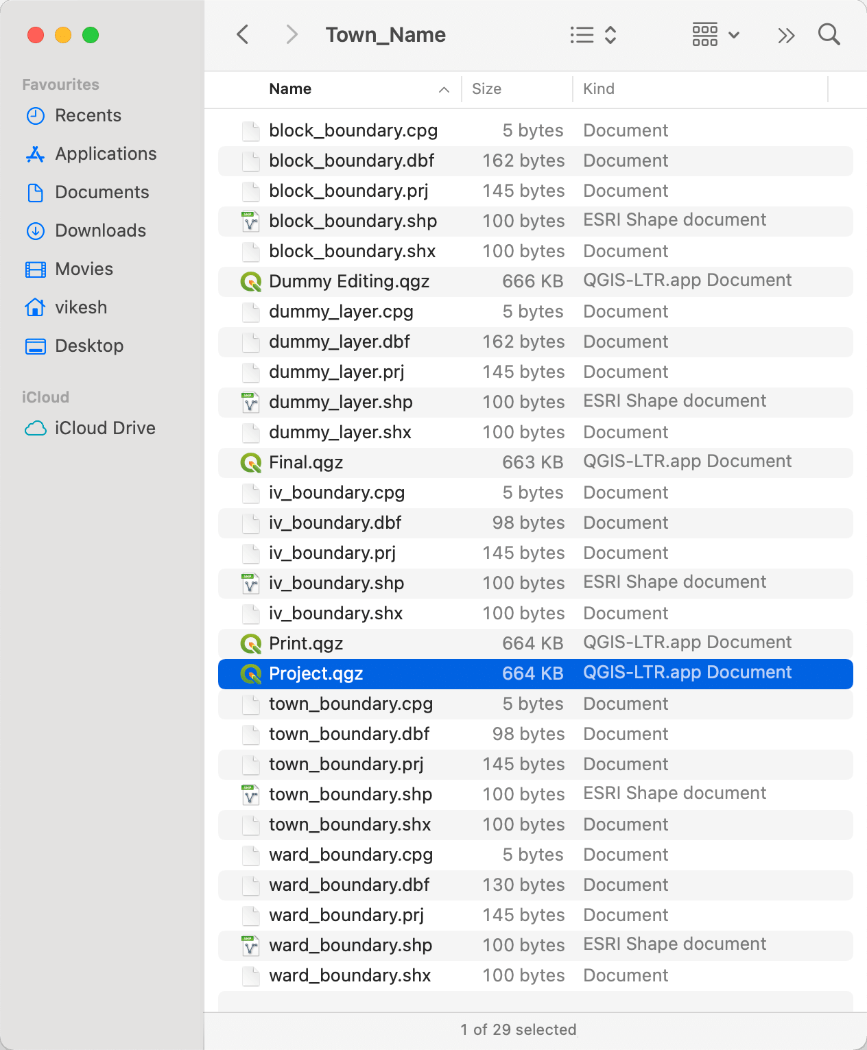
Here you will see four project files with the extension of qgz.
Open Project.qgz with QGIS
To create a new town, we will begin by opening the Project.qgz file. After QGIS opens, you shall see four vector layers and two map layers in the layer panel:
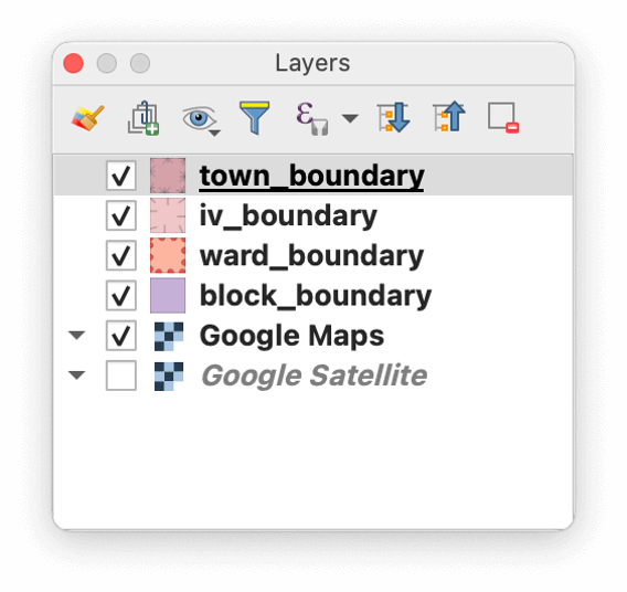
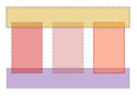
Each of these layers have been styled in different style of boundary and color fills, so that they are easy to distinguish from each other:
You may optionally log in to the official plugin. Now, zoom in to the desired location to begin making the map.
Begin drawing the map
To begin drawing the map, make the block_boundary layer as active and then toggle editing for this layer by pressing the pencil icon.
Next, grab the create feature tool and begin drawing the block boundary for each layer. It is important to note that the blocks are exclusive and exhaustive features for any town. The Avoid overlap on active layer options has already been activated, so you will not have to worry about any overlapping. Just draw the blocks, in such a way that there is no gap between any two adjacent blocks.
For drawing, you can also make use of above features by drawing into the already created features to automatically let QGIS snap the already drawn boundaries for your feature, as shown in the clip below:
After you have drawn all the blocks for the concerned town, it is now time to check if any gaps and overlaps still exist. This exercise is only meant to reduce the number of errors that may have crept in while drawing the maps.
If you have already drawn the block boundaries in some other project or projects, the steps required to be followed are briefed in another part of this manual. After completing those steps, you may continue following steps from here.
Before you proceed, save any changes you have already made in both the project and the block boundary as well. Since, the next requires use of different project, you should close this project and hit Save on any dialog that appears.
Also, it is advised that before you proceed make sure to have a backup in case anything wrong happens with the project.
Checking for gaps in features
For checking gaps between features, we will use the second project in this template called Dummy Editing.qgz. Open this project with QGIS and in the layers panel you should see an additional layer called dummy_layer. This layer shall be used exclusively to remove gaps and will be used as a guide for this purpose only. You need not to save any changes made to this layer throughout the project.
Now, since the project only contains features in the block boundary layer, we can zoom in to the desired position by right clicking the block_boundary in layers panel and choosing Zoom to layer from the context menu. This shall zoom in to the features that you have already drawn or imported from other layers.
So, let's begin.
Open the attribute table of the blocks layer by right clicking on the block_boundary in layers panel and choose Attribute Table from the context menu.
This shall open a new window with list of features present on the current boundary. Now, select all the features by pressing the button in the toolbar given in the top of the window (hover over different buttons to see what they do). After all features are selected, press the button from the toolbar to copy all the features to clipboard. Then close this window.
Do not use keyboard shortcuts to select all or copy the features, as it may lead to unexpected behaviour. Always use the buttons provided in the toolbar to perform the desired operation.
Next, open the attribute table of the dummy_layer and then paste the copied features into this layer. Before copying, make sure that the active layer is dummy_layer, it is set to be editable and there are no other existing features in this layer (if there are, then delete them first before pasting new features).
After all the features are pasted into the dummy layer make sure the active layer is dummy layer (and it is visible) and then select all features of dummy layer and open the Edit menu from QGIS window. Then select the Merge Features option present in the lower part of this menu.
You shall see a dialog box asking you to merge features, press Yes to proceed and then you shall have a single feature in the dummy layer.
However, if you don't see the dialog box and see a message on a red banner instead, then you need to manually select multiple features at a time and merge them into single feature.
After, all features have been merged into a single feature on the dummy layer, you shall see gaps (if any) in the layer. There shall be mainly three type of gaps that may exist:
- Presence of additional vertex: This may be the case when there exists an additional node which is not present in the adjacent feature. The solution to this type of gap is simply to identify the additional node and delete it from the original block layer using the dummy layer as the guide.
- Presence of visible gap: This may happen if the QGIS did not snap the nodes onto each other. To remove this type of gap, turn on the maps layer and identify which node needs to be moved to fill this gap. And then move the node from the original block layer using the dummy layer as the guide.
- Snapping on straight line of another feature: This case may be tricky to solve, as there is no gap between the two (or more) features but a theoretical mismatch between number of nodes at intersection of any two adjacent blocks. To fill this gap, you will need to create an additional node in the straight line and snap it onto the point of intersection.
Note: The use of dummy layer in above case is merely to be used as a guide to see where the gaps exists. Any editing is to be carried out in the original block layer, as the gaps may be left if you accidentally edit the dummy layer while leaving the block layer unchanged.
Now, this process of checking gaps and removing them using the dummy layer as a guide is to be repeated as many times as required until there are no gaps left to remove.
So, after each iteration, you will need to copy all the features again from block layer, empty the dummy layer and then paste those features into the dummy layer. Then merge these pasted features into a single feature in the dummy layer and check for gaps again. After removing the gaps, save the block layer and repeat the process until there are not gaps in the block layer.
Removing overlaps
After all the gaps have been removed, you will need to get rid of the overlaps that exist in the block layer.
First of all, deselect all the features from each layer, so that overlaps will be visible easily due to transparency of the block layer. Also, turn off the Google Satellite and Google Maps layer to have a better view. The overlapped parts will appear darker than the normal part of the block boundary layer.
Before beginning with the faster method to remove gaps, you must ensure that the layer does not contain any larger overlaps that may need your attention. Briefly view the block boundary once and you will be able to find out if any large overlaps exist in the layer. Remove such overlaps by manually moving the overlapped part into only one feature/block. Make sure that you do not create any gap while removing this overlapping, as it may become problem on a later stage.
After large overlaps have been removed and no gaps are present in the layer (to check use the process described above once more for certainty), we can begin to remove the overlaps by following the process described below:
- Open the attribute table of block layer and make sure editing is enabled
- Arrange all the features according to a single attribute (choose record number, as it will be unique for each block) by clicking on the attribute in the header of the feature table
- Now, select the first feature by clicking the number 1 in the left most corner of the attribute table
- After the first feature is selected, use the toolbar button to cut the feature
- Then paste the feature again using the button given in the toolbar
- Repeat the above process of selecting, cutting and then pasting the feature back for each feature in the block layer
Warning: Do not paste one feature multiple times in the same layer, as it will be collapsed and it may become difficult to identify the feature which has been wrongly pasted.
The above process can be carried out in the dummy project or even the actual project file.
This process will remove all the existing gaps in the layer and you shall now have the layer free of any gaps as well as overlaps. Now, this layer can be used to create higher layers by merging features from this layer.
Migrating from older projects
If the data for block boundary has already been drawn in an older project format, or you have multiple projects for each ward or iv unit, then you need to import the data from those into this template using the procedure described below.
Importing existing data
There are two approaches to handle this:
- First is by opening both projects side by side (project from this template and existing project).
- And, second is by dragging shape files as needed from older project to QGIS window of this project.
Here, using the second approach has a few benefits over the first approach:
- Since, the shape files are version independent, work done in higher versions of QGIS (above 3.16) will not create problems by not opening in QGIS 3.16
- All the shape files will be known before hand to exist in single directory, so no problem of unhandled layers
- There will be no accidental edits to the original project, so in case any thing happens to final project, older project is safe
So, this manual will be using the latter approach to perform this migration process. First, the process to migrate a single layer town will be explained and then it will be advanced to accommodate for the second layer as well.
Importing from single project
Open the project using the Project.qgz file and a QGIS window should open up.
Next, open the folder where the block boundary layer for this town exists. The file name must end in .shp for the shape file and you will see the description of the file as ESRI Shape Document.
After you have located the shape file of blocks, drag and drop it onto the QGIS window opened up earlier. After dropping it, you should see a new layer in the layers panel of QGIS with the same name as of the shape file.
Open the attribute table of this dropped layer by selecting Attribute table from the context menu. Make sure that the attributes in this layer are named as b for block number, w for ward number, iv for iv unit number and recordNo for record number of the feature. If this is not the case, then you need to modify this by using the following procedure:
Renaming attributes for existing layer
- Close the attribute table of this layer and open properties of this layer
- Open the field panel of this layer from the opened dialog box and you will see the list of fields for this layer
- Enable editing for the layer and change the existing attributes by double clicking on the names of attributes
- After all attributes have been changed to desired values, click Ok button to close the dialog box
Make sure that the type of attributes in this layer is given as integer for each of the attribute. If not, you will need to use the Field Calculator to change the type of field to integer. The length will work for this procedure, even if it is different from the one described in the guidelines.
After renaming the attributes (if required), open the attribute table of the imported layer. Then, select all features and copy them using the buttons given in the toolbar. After copying these features, close this attribute table.
Now, open the attribute table of block_boundary layer that already existed in the project and paste all the copied features into the attribute table of this layer.
If the pasted features have any value as NULL, then this means that the attributes of the features have not been renamed properly. Delete all the pasted features and follow the procedure described above again to make sure all the attributes have right values and type before pasting the data next time.
Now, remove the dragged layer from this project without saving any changes to that layer. To remove, right click on the dragged layer from panels window and then select Remove layer from the context menu.
You might see a dialog box asking you to save changes to the layer. Click on Don't save button, as we need the imported file to stay as it was before we started this process. Following this you will see a dialog box to confirm removal, click ok to remove this layer.
Next, save the changes to the block_boundary layer of this project, as we have all the required features in this layer now to begin working.
Now, begin the process of removing gaps and overlaps from the layer as described in the sections above.
Importing from multiple projects
Importing from multiple projects is similar to importing from single project, except in the way that you will have to drag and drop files from multiple projects.
You will also need to make sure that there are no overlaps among these multiple projects.
First of all, take the first project and drop the file onto the QGIS window. Repeat the procedure as described above for a single project.
After pasting the features, drag and drop the second shape file (for block boundary only) from different project which is adjacent to the block files of earlier shape file and before going for copying the features, you will need to make sure manually that there are no large overlaps or gaps between these two shape files.
To see the overlaps more clearly, you will have to change the transparency of the dropped layer by opening its properties and changing it from the Symbology tab. Keep the transparency somewhere between 35-70% for optimal results.
Remove all the gaps from layers as required. If the overlap exists due to error in this second project, modify the dragged file to adjust for the overlap. However, if the gap is due to error in earlier project, change the block_boundary to accommodate for removal of overlaps. After the overlap has been removed and there are no huge gaps, copy all the features from the second project and paste them into the block boundary layer of this project. And then remove the dragged layer without saving any changes.
Repeat this process for all the projects by removing the gaps and overlaps if any in the final project.
After all the block layers have been pasted into the block boundary layer, save it first and continue with the process as it was done for a single project i.e., begin the process of removing gaps and overlaps from the layer as described in the sections above.
Creating higher layers
After all the inconsistencies in block layer have been removed including overlaps and gaps, the formation of higher layers can be started. The process will be same for creating IV Unit Layer and Ward Layer from Block Layer. And then at the end, the town layer can be created from merging features of any of the three layers.
But, before continuing with the merging process, make sure that all the dummy numbers have been removed. This process can be done after merging as well, but then you will have to replace the dummy number in blocks as well as iv unit layers separately.
Replacing dummy numbers using Print.qgz
To change dummy numbers, we will need to use the Print.qgz project. Save all the changes to this project and close it. Next, open the Print.qgz project and Zoom to layer from the context menu of block boundary layer.
Now, press Control + P and give a name to this layout. Next, add a map object to the page opened and drag the map covering the full view size. Then save the output in a PDF file from the tool bar button.
Take a print out of this PDF file and assign the final block numbers in the clockwise spiral order starting from block in north west as one in increasing order.
Next, close the print project and open up the Project.qgz again. Then, assign the final block numbers in the attribute table of block layer. And then save the changes to this layer and project.
Merging layers
To merge layers for forming higher layers, we will begin by creating IV Units from blocks. To do this, open the attribute table of block boundary layer and copy all the features using the button provided in the toolbar.
Next, make sure that IV Unit Boundary is visible and then open its attribute table and enable editing for this layer. Now, paste the copied features into this layer using the button from the toolbar. Then, sort the features using iv unit number by clicking iv in the table header.
Now, select features by clicking dragging the mouse in the numbers in the extreme left of attribute table window for one iv unit at a time. You can also select the features belonging to one IV unit using the Select features button given in tool bar and entering the desired IV Unit number.
Now, merge these features using the merge option in the Edit menu. Keep merging features belonging to one IV unit into a single feature.
At last, replace the record numbers with the record numbers from the portal and save the layer as well as the project.
The same procedure can be repeated for wards by doing the work for wards instead of IV unit.
Similarly, the town boundary can be prepared by copying all the IV Units and then merging them into a single boundary in the town layer.
Finishing up
Now, the project is finished and is ready for upload. A few notes regarding this project are described below.
Case of census town
In case of a census town, there is no provision for ward boundary. So, the layer ward boundary can be removed from the project easily (all four projects). All the other features are similar to that of a statutory town. The attribute table of block boundary will have ward numbers as 999. And rest of procedure to be followed will be the same.
Readying for upload
The boundaries can be uploaded using the upload tool easily. To do so, make a copy of the whole folder to some place other than its current location.
Now, open the Project.qgz file. After QGIS opens up, open the properties of each layer (block, iv unit, ward and town boundary) and rename the recordNo field to rn. Then delete all other fields and save the layers and project after all this is done.
Next, use the upload tool to select each layer one by one and then upload after entering proper credential in the upload tool.
Moving the project around
Since, all the files of this project are located in a single folder, it can be easily moved around and copied from one location to another location including external storage e.g. pen drives. This will not create any problem like any missing layers or blue/black screen when loading Google Maps or Satellite.
 Portal Editor
ufs.vikesh.me
Portal Editor
ufs.vikesh.me